Chongfan Technology
News
25
2026
-
02
Utilizing Trivial Bundles to Control Photonic Topological Edge States and Corner States
Author:
The research teams led by Professor Wang Haixiao from Ningbo University, Professor Pu Yin from Nanjing University, and Professor Jiang Jianhua from Soochow University have innovatively proposed using a trivial cladding as a new degree of freedom for tuning topological photonic states. By designing Kagome photonic crystals with either C6 or C3 crystal symmetry, they have constructed a topologically nontrivial quantum spin-Hall phase together with a tunable trivial-cladding structure. Through precise adjustment of the geometric parameters of the trivial cladding, the team has achieved active control—both theoretically and experimentally—over the band structure of topological interface states, inducing a topological phase transition characterized by a reversal of the Dirac mass sign. In the process, they have also successfully controlled the emergence and annihilation of higher-order topological corner states within hexagonal supercells. This work not only reveals the crucial role of the trivial cladding in the formation and phase transitions of topological boundary states but also provides a novel geometric approach for dynamically controlling topological light fields—for instance, in rainbow trapping applications.
The research findings were published on January 31, 2026, in Laser & Photonics Reviews under the title “Manipulation of Photonic Topological Edge and Corner States via Trivial Claddings.”

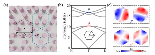
Figure 1: (a) Schematic diagram of topological isomers based on the Kagome photonic crystal, showing three unit-cell configurations located at different Wyckoff positions: H-KPCs, U-KPCs, and D-KPCs. (b) Band structure of the Kagome photonic crystal. Note that only in H-KPCs does the parity of states at the Γ point have a well-defined character. (c) Electric-field distributions of two pairs of degenerate modes at the Γ point, exhibiting odd parity (top figure) and even parity (bottom figure), respectively.
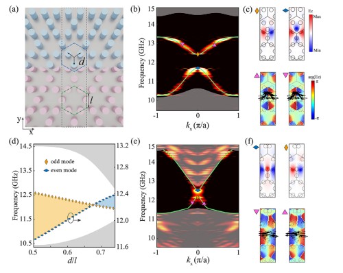
Figure 2: (a) Schematic illustration of the domain-wall structure formed by H-KPCs and D-KPCs with different geometric parameters, θ. (b) Simulation and experimental results of the edge dispersion relation of the domain wall formed by H-KPCs and D-KPCs when θ = 0.5θ. (c) Top panel: Electric-field distribution of the edge state at ϕ = 0. Bottom panel: Phase distribution and Poynting vector of the edge state at ϕ = 0.1θ/λ. (d) Evolution of the frequency gap as a function of the geometric parameter θ. The gray area represents the bulk states. (e) Simulation and experimental results of the edge dispersion relation of the domain wall formed by H-KPCs and D-KPCs when θ = 0.75θ. (f) Top panel: Electric-field distribution of the edge state at ϕ = 0. Bottom panel: Phase distribution and Poynting vector of the edge state at ϕ = 0.05θ/λ.
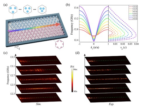
Figure 3: (a) Experimental photograph demonstrating topological rainbow trapping at the interface between H-KPCs and D-KPCs. (b) Dispersion relation of the branch states on the topological interface (left) and the corresponding group velocity (right), as a function of different geometric parameters. (c) Normalized electric field intensity distributions of the ϕϕ component at various frequencies, as obtained from simulations. (d) Normalized electric field intensity distributions of the ϕϕ component at different frequencies, as measured experimentally.
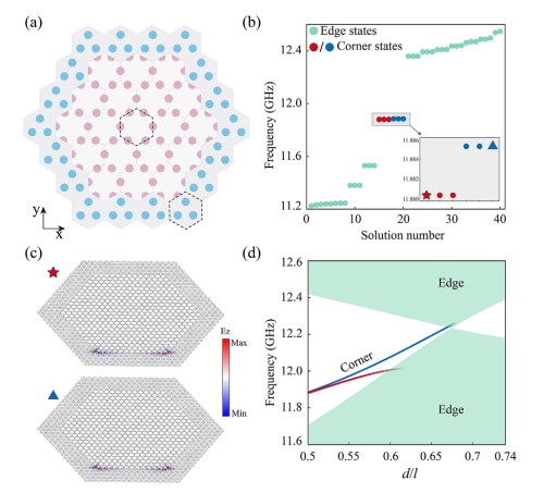
Figure 4: (a) Schematic diagram of the 3-fold symmetric supercell, in which H-KPCs are surrounded by U-KPCs. (b) The eigen-spectrum of a finite-size supercell. Edge states and corner states are indicated in green and blue (red), respectively. (c) Typical electric field distributions of two corner states. (d) Evolution of corner states as a function of the geometric parameter θ.
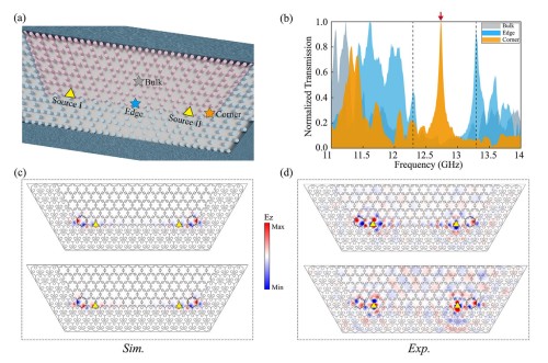
Figure 5: (a) Schematic diagram of a semi-hexagonal structure composed of H-KPCs (inner layer) and U-KPCs (outer cladding), designed for observing corner states. (b) Transmission spectra measured using three pump-probe configurations: bulk state—gray, edge state—blue, and corner state—orange. (c, d) Electric field distributions of the corner states, showing simulation results (c) and experimental results (d), which exhibit excellent agreement.
Source: Metasurface Optics
Previous
Previous
LATEST NEWS
Thank you for visiting the official website of Chongfan Technology. If you have cooperation intentions or suggestions, please contact us through the following methods, and we will reply as soon as possible, thank you!
Address: Room 403, Building 6, Phase III of R&D, No. 36 Xiyong Avenue, High tech Zone, Chongqing, China.
Telephone: +86-13658337211
E-mail: Sales@cfkeji.net
Website: www.cfkeji.net
Mobile Version