
Chongfan Technology
Products
Product

Scanning lens
Classification:
Detail
Parameters
Technical Data
Product Description
● Telecentric optical path and f-theta aberration correction design
● Flat-field uniformity, enhancing imaging consistency
● Can be used in combination with a tube lens, objective lens, and other components.
Chongfan Technology’s scanning lenses are core optical components in laser scanning systems, typically used in conjunction with galvanometer scanners. Their operating principle is based on two key functions: flat-field focusing and linear scanning. By employing a multi-element lens design, these lenses introduce controlled negative distortion to correct the focal plane into a flat surface, while maintaining a linear relationship between the spot position (y) on the focal plane and the beam deflection angle (θ), expressed as y = f × θ (where f is the lens focal length). Furthermore, the lenses adopt an image-space telecentric optical path, ensuring that the chief rays in the image space remain parallel to the optical axis. This guarantees consistent chief-ray incidence angles and uniform illumination across the entire field of view. Combined with full‑field aberration correction, they enhance the uniformity of spot size and the consistency of imaging resolution throughout the field, meeting the stringent precision‑scanning requirements of advanced imaging applications such as OCT and confocal microscopy. Chongfan Technology offers scanning lenses with a variety of scan angles and scan formats, available in wavelengths ranging from 400 to 1800 nm and focal lengths from 18 to 110 mm. Customers can select the configuration best suited to their specific needs; for more details, please contact Chongfan Technology’s technical support.

Scanning lenses are widely used in laser scanning microscopy systems.
● Designed for laser scanning microscopy systems
● Scanning angle: ±7.8° x ±7.8°, ±8.1° x ±8.1°
● Thread specifications: SM30, SM2
Chongfan Technology’s scanning lenses employ a telecentric optical path and f-theta aberration correction, converting changes in galvanometer scan angles into linear displacements on the focal plane to suppress geometric distortion and deliver a flat image plane. This product series is primarily designed for laser scanning microscopy systems and can be paired with tube lenses and objective lenses to achieve a telecentric imaging optical path. Operating wavelengths span from the visible to the near-infrared, with options including 400–750 nm, 450–1100 nm, 680–1300 nm, and 800–1800 nm, allowing selection based on specific application requirements.


The scanning lens is mounted on the five-axis adjustment mount AMM5-1AC via a threaded adapter.

Scanning lenses are widely used in OCT systems.
● Designed for OCT imaging systems
● Scanning angle: ±7.5° × ±7.5°, ±10.0° × ±10.0°
● Thread specifications: M25×0.75, SM2
Chongfan Technology’s scanning lenses employ a telecentric optical path and f-theta aberration correction, converting changes in galvanometer scan angles into linear displacements on the focal plane to suppress geometric distortion and deliver a flat image plane. This product series is designed for OCT systems but can also be used in laser‑scanning microscopy. Available operating wavelength ranges include 400–700 nm, 750–950 nm, 800–1100 nm, 950–1150 nm, and 1250–1380 nm, allowing selection based on specific application requirements.


The scanning lens is mounted on the five-axis adjustment mount AMM5-1AC via a threaded adapter.

I. Product Introduction
The scanning lens is a core optical component in laser scanning systems, typically used in conjunction with galvanometer scanners. Its operating principle hinges on two key functions: flat-field focusing and linear scanning. When a laser beam, deflected by the galvanometer scanner, enters the scanning lens, a conventional lens would focus the beam onto a spherical image plane, inducing field curvature. This results in enlarged spot sizes at the scan edges and degraded image quality, as illustrated in Figure 1‑1. By employing a multi-element lens design that introduces controlled negative distortion, the scanning lens corrects the focal plane to a flat surface while maintaining a linear relationship between the spot position (y) on the focal plane and the beam deflection angle (θ), expressed as y = f × θ (where f is the lens focal length). Furthermore, the scanning lens adopts an image-space telecentric optical path, ensuring that the chief rays in the image space are parallel to the optical axis, as shown in Figure 1‑2. This design guarantees consistent chief-ray incidence angles and uniform illumination across the entire field of view. Combined with full-field aberration correction, it delivers uniform spot sizes and consistent imaging resolution, meeting the stringent precision‑scanning requirements of advanced imaging applications such as OCT and confocal microscopy.
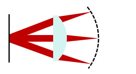
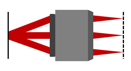
Figure 1-1 Focusing with a conventional lens Figure 1-2 Focusing with a scanning lens
II. Product Features
- Full-Field Spot Uniformity Optimization: The consistency of the image‑plane spot size across the entire field of view has been optimized, with center‑to‑edge transmittance uniformity exceeding 98%. This ensures uniform illumination across the sample’s full field of view and stable imaging resolution, effectively mitigating edge‑of‑field image degradation.
- Telecentric optical path and f-theta aberration correction design: When the angle of incidence varies, it produces a flat image plane, effectively suppressing geometric distortion and enabling direct output of geometrically corrected scan images without extensive post-processing.
- Broadband Adaptation and Anti-Reflection Coating Technology: Covers multiple spectral bands from visible light to the near-infrared, with broadband dispersion correction achieved through optimized design; a full range of anti-reflection (AR) coatings is available, significantly reducing back reflections from broadband light sources.
- System Compatibility and Scalability Design: It can be seamlessly integrated with aberration‑correcting tube lenses, compatible with galvanometer scanners of various specifications and infinity‑corrected optical systems, thereby meeting the integration requirements of diverse application scenarios.
III. Parameter Description
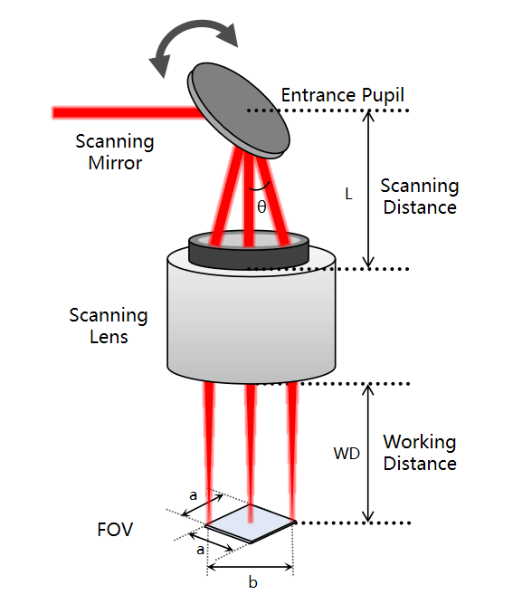
Figure 2: Description of Scanning Lens Parameters
- Entrance Pupil: This is related to the scanning galvanometer. For a single-mirror galvanometer, the entrance pupil is located at the mirror’s axis of rotation; for a dual-mirror galvanometer, the entrance pupil lies between the two mirrors.
- Scanning Distance L (Scanning Lens): The distance from the entrance pupil to the bottom end face of the scanning lens’s threaded section.
- Scanning angle θ: In the figure, θ denotes the one-dimensional scanning angle of the scan lens, which is twice the galvanometer deflection angle. The one-dimensional scanning range corresponding to ±θ is the diagonal b of the square scan field, while the two-dimensional scanning range corresponding to the two-dimensional scanning angle is a × a, where a is the side length of the square scan field.
- Working Distance (WD): The distance from the rear mechanical surface to the back focal plane.
Previous
Previous
Other Products
I want to consult
Thank you for visiting the official website of Chongfan Technology. If you have cooperation intentions or suggestions, please contact us through the following methods, and we will reply as soon as possible, thank you!
Address: Room 403, Building 6, Phase III of R&D, No. 36 Xiyong Avenue, High tech Zone, Chongqing, China.
Telephone: +86-13658337211
E-mail: Sales@cfkeji.net
Website: www.cfkeji.net
Mobile Version