Chongfan Technology
Products
Product

High-Power Beam-Splitting DOE
Classification:
Detail
Parameters
Technical Data
- UV‑fused quartz material with a surface relief microstructure.
- It can achieve uniform beam splitting in one or two dimensions, with either odd or even numbers of output beams.
- High beam uniformity, high angular separation accuracy, and high damage threshold.
- Operating wavelength: 355 nm & 343 nm
- Supports flexible customization of parameter specifications.
Chongfan Technology’s high‑power beam‑splitting DOE is a diffractive optical element fabricated from ultraviolet‑grade fused silica. By allocating energy across the desired diffraction orders, it achieves the intended beam‑splitting performance. Based on the required splitting pattern, spot spacing, or beam separation angle, its phase profile is designed according to diffractive optics principles, and a surface relief structure is then introduced via advanced fabrication techniques to realize the specified beam‑splitting function. Owing to its superior beam‑splitting uniformity and precise angular separation, this high‑power DOE is well suited for a wide range of applications, including parallel laser processing, optical sensing and detection, photomedicine and aesthetic treatments, and microscopic imaging. Compared with liquid crystal polymers, ultraviolet‑grade fused silica exhibits low UV absorption, making it more compatible with UV‑band applications. Chongfan Technology offers standard high‑power beam‑splitting DOEs operating at 355 nm and 343 nm, with multiple splitting configurations available. In addition to these off‑the‑shelf products, we also provide flexible customization of key parameters; please contact Chongfan Technology’s technical support for detailed customization requirements.
High-power beam-splitting DOE, 355 nm, one-dimensional beam splitting
- Operating wavelength: 355 nm
- Splitting modes: 1×2, 1×3, 1×4, 1×5
- Ultraviolet-fused quartz material
Chongfan Technology’s high-power beam‑splitting DOE is fabricated from UV‑fused silica using a surface‑relief grating process, enabling one‑dimensional beam splitting with ratios of 1×2, 1×3, 1×4, and 1×5. The device features an effective clear aperture of 15 × 15 mm and is mounted in a matched 1‑inch mechanical housing, whose exterior bears the product model number. Unless otherwise specified, the engraved side typically corresponds to the recommended beam‑incident face, facilitating installation, alignment, and operation for users.
High-power beam-splitting DOE, 355 nm, two-dimensional beam splitting
- Operating wavelength: 355 nm
- Beam-splitting mode: 5×5
- Ultraviolet-fused quartz material
Chongfan Technology’s high‑power beam‑splitting DOE is fabricated from UV‑fused silica using a surface‑relief patterning process, delivering a 5×5 two‑dimensional beam‑splitting pattern. The device features a 15×15 mm clear aperture and is mounted in a compatible 1‑inch mechanical housing, with the product model engraved on the housing surface. Unless otherwise specified, the engraved side typically corresponds to the recommended beam‑incident face, facilitating installation, alignment, and operation for users.
High-power beam-splitting DOE, 343 nm, one-dimensional beam splitting
- Operating wavelength: 343 nm
- Splitting modes: 1×2, 1×3, 1×6, 1×20
- Ultraviolet-fused quartz material
Chongfan Technology’s high‑power beam‑splitting DOE is fabricated from ultraviolet‑grade fused silica using a surface‑relief patterning process, enabling one‑dimensional beam splitting with ratios of 1×2, 1×3, 1×6, and 1×20. For the 1×2, 1×3, and 1×6 configurations, the clear aperture is 15 × 15 mm; for the 1×20 configuration, it is 17.5 × 17.5 mm. The devices are mounted in a matching 1‑inch mechanical housing, with the model number engraved on the housing surface. Unless otherwise specified, the engraved side typically corresponds to the recommended beam‑entry face, facilitating installation, alignment, and operation.
Chongfan Technology High-Power Beam-Splitting DOE – Technical Description
I. Overview
Chongfan Technology’s high‑power beam‑splitting DOE is a diffractive optical element fabricated from ultraviolet‑fused silica. It achieves the desired beam‑splitting performance by distributing energy across the relevant diffraction orders. Based on the required beam‑splitting pattern, spot spacing, or beam‑separation angle, its phase profile is designed according to diffractive optics principles, and the designed phase structure is then imprinted using a surface‑relief fabrication process. Owing to its superior beam‑splitting uniformity and precise separation angles, this high‑power DOE is well suited for a wide range of applications, including parallel laser processing, optical sensing and detection, and laser‑based medical and aesthetic treatments. Compared with liquid‑crystal polymers, ultraviolet‑fused silica exhibits low absorption in the UV spectral region, making it more compatible with UV‑band applications.
For odd‑order beam splitting, the zeroth‑order beam is output as one of the split beams, and the separation angle is defined as the angle between the zeroth‑order diffracted beam and the first‑order diffracted beam. For even‑order beam splitting, the zeroth‑order beam does not contribute to the final output, with its energy distribution approaching zero, and the separation angle is defined as the angle between the ±1st‑order diffracted beams.

Figure 1 Schematic of the separation angle for odd/even beam splitting
II. Product Structure
Chongfan Technology’s high‑power beam‑splitting DOEs are fabricated from ultraviolet‑grade fused silica using a surface‑relief grating process, enabling one‑dimensional or two‑dimensional beam splitting of the incident spot. Most standard high‑power beam‑splitting DOE elements measure 16 × 16 mm with a clear aperture of 15 × 15 mm; the DOE25Q‑343‑BS1X20‑DEG00005 model features dimensions and a clear aperture of 17.5 × 17.5 mm. All standard products are mounted in a Ø25.4 mm mechanical housing and are compatible with standard 1‑inch optical component mounts. The exterior of the housing is engraved with the company logo and the corresponding product model number; unless otherwise specified, the engraved side typically corresponds to the recommended beam‑incident surface, facilitating easy identification during alignment and setup.
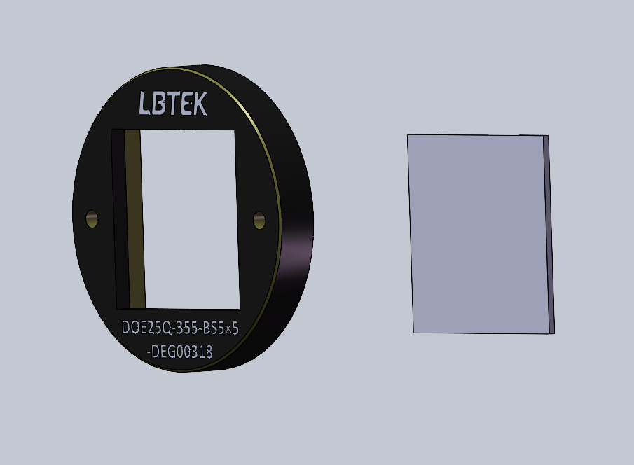
Figure 2 Schematic diagram of the product structure of a high-power beam-splitting DOE.
III. Product Performance
1. Maximum separation angle
The maximum separation angle of Chongfan Technology’s high-power beam‑splitting DOE is one of the performance limits imposed by the manufacturing process. This maximum separation angle is determined by the maximum diffraction angle, which in turn depends on the periodic phase profile of the beam‑splitting DOE and satisfies the grating diffraction equation:

Here, m denotes the diffraction order, λ is the operating wavelength, p is the period of a single grating cycle, and θ is the diffraction angle of the m-th order beam (the angle between the m-th order diffracted beam and the optical axis). If you require a beam‑splitting DOE with a larger separation angle, please contact LBTEK technical support in advance to confirm whether the manufacturing process can meet your specifications.
2. Working Distance
For high-power beam‑splitting DOE standard products, when a collimated beam is incident, the beam is split and exits at the specified separation angle. At short transmission distances, due to the finite size of the input beam, the split beams overlap, making it difficult to distinguish individual spot patterns. Only after propagating over a certain distance do the split beams become sufficiently separated. Consequently, the effective working distance is primarily determined by the input beam diameter and the separation angle.
If no lens is added after the beam-splitting DOE, the optical path is as shown in Figure (a). At the working distance, the spot spacing D, the working distance L, and the separation angle θ satisfy the following relationships:
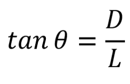
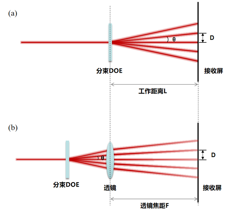
Figure 3 Schematic diagram of direct beam splitting and lens-assisted imaging at the focal plane.
To achieve focused spot beam splitting at a specific working distance, a focusing lens matched to that working distance can be incorporated into the design. As shown in Figure (b) above, the spot spacing D, the lens focal length F, and the separation angle θ at the working distance satisfy the following relationship:
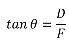
The size of the focused spot at the working distance is close to the diffraction-limited size DL:

Note that if the system is used in conjunction with a galvanometer scanner, a field lens, or other optical elements, the output aperture of these components must not truncate the beam‑splitting spot; otherwise, the uniformity of the split beam will be significantly compromised.
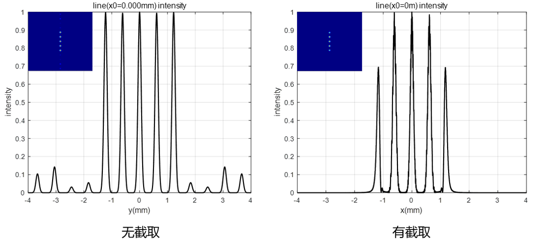
Figure 4: Simulation examples of optical components in the optical path, showing beam splitting with and without truncation of the split spot.
3. Influence on the Energy Distribution of the Incident Light Spot
In general, the beam incident on a beam-splitting DOE should be collimated. The beam-splitting DOE only splits the energy; it does not affect the beam’s spot‑size distribution or other spatial characteristics.
IV. Parameter Description
1. Separation Angle
For a beam‑splitting DOE, the separation angle refers to the angular spacing between two adjacent output beams in the one‑dimensional direction; its precise definition is shown in Figure 1. The accuracy of this parameter depends on both the number of beams and the beam‑splitting angle: the greater the number of beams and the larger the splitting angle, the larger the associated error.
2. Diffraction Efficiency
The diffraction efficiency of a beam-splitting DOE is defined as the ratio of the total intensity of the split beams to the total intensity of the output light.

3. Beam-splitting uniformity
The beam-splitting uniformity, denoted as uni, of a beam-splitting DOE is defined as:

Among them, I max For the maximum light intensity in each beam-splitting spot, I min It is the minimum light intensity in each beam-splitting spot.
4. Minimum Incident Spot Diameter
The minimum spot size of the incident beam is related to the design parameters of the beam‑splitting DOE; typically, the minimum spot size should be at least three times the period of the DOE. According to the grating diffraction equation, it is determined by the operating wavelength and the angular separation.
Furthermore, the maximum incident spot size is limited by the clear aperture; it is recommended that the incident spot size be less than 90% of the clear aperture.
Previous
Next
Previous
Next
Other Products
I want to consult
Thank you for visiting the official website of Chongfan Technology. If you have cooperation intentions or suggestions, please contact us through the following methods, and we will reply as soon as possible, thank you!
Address: Room 403, Building 6, Phase III of R&D, No. 36 Xiyong Avenue, High tech Zone, Chongqing, China.
Telephone: +86-13658337211
E-mail: Sales@cfkeji.net
Website: www.cfkeji.net
Mobile Version